Introduction
The working width of a safety barrier constitutes one of the crucial design parameters when roadside design is carried out (Troutbeck, 2022b). The working width value of a specific safety barrier product is determined by a crash test, subject to test level (Austroads, 2024). The Manual for Assessing Safety Hardware (MASH) (AASHTO, 2016) is a United States of America (USA) crash testing protocol to identify the containment level of road safety barrier systems and has been adopted in Australia at both the federal and state government levels. Through a series of MASH tests, the working width subjected to the test level can be recorded and referred by road design practitioners to consider the minimum offset from the traffic face of the safety barrier to the furthest point behind the barrier where no objects should exist (Troutbeck, 2022b). Due to a strict safety barrier product approval process and supplier registration scheme implemented in most state jurisdictions in Australia, all the accepted proprietary safety barrier products have their design parameters including working widths disclosed to the public. However, the working width of a public domain extruded single slope concrete barrier was historically reliant on state road authorities published design manuals or guidelines. For this project, conducted in Queensland, the document of interest was the Road Planning and Design Manual (RPDM) produced by the Queensland Department of Transport and Main Roads (TMR) which provides Queensland specific design requirements to supplement the Austroads Guide to Road Design (AGRD) series (TMR, 2020).
The superseded RPDM 2nd Edition, Volume 3, Part 6 (TMR, 2014a) suggested a working width of 900 mm for the public domain single slope concrete at the speed of 100 kilometres per hour (km/h) with a crossfall of 3 percent on the ground surface. The recent version of RPDM Volume 3, Part 6 (TMR, 2022) accepted the updated minimum working width values as indicated in AGRD Part 6 – Roadside Design, Safety and Barriers (Troutbeck, 2022b), which requires a working width of up to 2400 mm, subject to test level and barrier height. The superseded and current working widths for single slope concrete barriers are listed for comparison in Table 1.
It should be noted that the superseded working width values specified in the 2014 version of RPDM Volume 3 Part 6 were adopted directly from the dated Road Traffic Authority (RTA) of NSW Road Design Guide (RTA, 2000) that did not specify the original source of these working widths and that we were unable to locate or verify. Given that the original crash testing data to substantiate the working widths in NSW RTA Road Design Guide is untraceable, the updated working width values provided in the 2022 version of AGRD Part 6 were derived from the few credible crash tests available from the USA and therefore were deemed more reliable. In addition, the design vehicle used in the old standard does not represent the current motor vehicular features in Australia where heavy vehicles can reach 4600 mm high as regulated by the Heavy Vehicle National Law (HVNL) applied across most of Australian states since 2014 (NHVR, n.d.; Queensland Government, 2024).
It should be acknowledged that in practice the superseded design standards may have been adopted for a ready-to-construct project after publication of the new design guide. However, the design was valid at the time. For instance, a 900 mm working width was adopted for a Queensland road project and the design had been finalised prior to October 2022 when the new 2022 version of RPDM Volume 3, Part 6 was released. Whilst valid at the time, the 900 mm working width does not represent contemporary research findings and recommendations that have been nationally accepted. Hence, from an asset owner’s perspective, residual risks within the controllable range need to be managed and assessed.
When redesigning the cross sections is impractical due to site constraints like bridge piers, gantries, or pre-determined land resumptions, using a redesigned single-slope concrete barrier is an acceptable alternative. A working width of 900 mm in constrained designs can be achieved through a Design Exception by applying the concepts and working widths outlined in AGRD Part 6 (TMR, 2023b).
The aim of this study was to develop an alternative design methodology for the working width value of a specific safety barrier product to address the situations not covered by either the Normal Design Domain (NDD) or the Extended Design Domain (EDD).
Development of an alternative design methodology
Crash testing data selection
The safety barrier crash testing data selected for this study should meet the following three conditions: compliance with MASH standards, testing to TL-5, and a profile similar to TMR’s public domain single-slope concrete barrier. To meet these requirements, only two existing barrier tests were found and both were tested according to the Test 5-12 criteria. Test 5-12 requires a 36000V truck (36 tons in mass) to impact the test article at the angle of 15.00° at the speed of 80 km/h (ASSHTO, 2016).
One of the products was developed by the University of Nebraska-Lincoln, the USA (Rosenbaugh et al., 2007). The test was conducted to the NCHRP350 standards (Ross et al., 1993), but equivalent to MASH Test Level 5 (TL-5) in terms of the testing conditions. This tested barrier is different from the TMR public domain single slope concrete barrier as the former is much more vertical than the TMR one. This may cause less comparability if extrapolating for the height and working width of the TMR single slope barrier. Therefore, this test was not considered further.
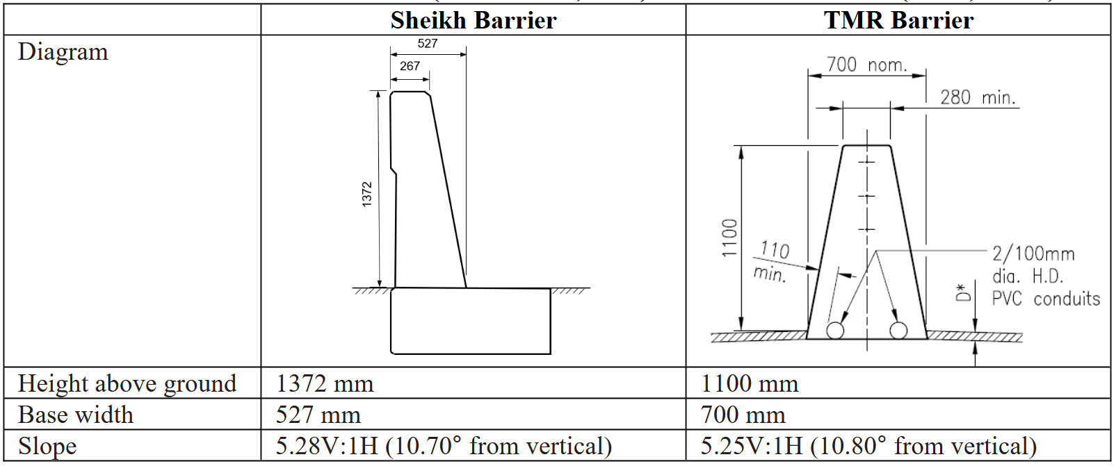
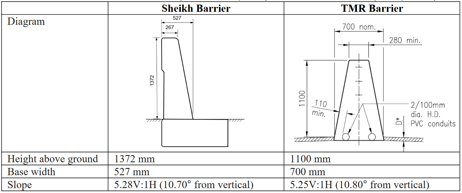
Another product was also designed in the USA (Sheikh et al., 2019), but it followed the standard MASH TL5-12 test, unlike the test conducted by the University of Nebraska-Lincoln. The test vehicle was 4060 mm high (Sheikh et al., 2019). This tested single slope barrier (Sheikh barrier) is different from the TMR public domain single slope concrete barrier (TMR barrier). The slope of the traffic face is very similar to the TMR barrier, except that the Sheikh barrier is taller i.e., 1372 mm versus (vs) 1100 mm. Consequently, the Sheikh barrier test has been chosen as the only comparable data to derive the required height of the TMR barrier for achieving 900 mm working width. The comparison in profile is illustrated in Table 2.
Method 1 – Linear extrapolation
The working width, as demonstrated in the test reported by Sheikh et al. (2019), is 1020 mm. This measurement aligns with the current definition of working width, which entails measuring from the outermost extremity on the traffic side of the safety barrier to the furthest extremity of any part of the system or vehicle during and after impact (Troutbeck, 2022b).
Notwithstanding that no formula was identified in academic publications that quantified the correlation between the vehicle height and the working width, jurisdictional guidance has been exercised in practice. For example, the Victoria State Government in Australia published a safety barrier design technical guideline including a “point of contact” method (Victoria DoT, 2023). The “point of contact” means drawing a straight line representing the vehicle roll line to contact two points of a F-shape concrete barrier at the kerb reveal and the top corner respectively (Victoria DoT, 2023). In this project, we had two assumptions: 1) its rationale is based on a negative correlation between the barrier height and the working width, and; 2) the vehicle height vs the working width follows a proportional relationship which was applied to adjust the vehicle height from 4060 mm (test vehicle) to 4600 mm (design vehicle).
As for the correlation between the barrier height and the working width, we did not identify any published research that directly explored this relationship. However, indirect justification can be drawn from a study by Sheikh et al. (2012) who undertook computer simulation Test 4-12 with a 10000S truck (10 tons in mass) impacting single slope concrete barriers with heights of 915 mm, 940 mm, 965 mm, 991 mm, and 1067 mm at an angle of 15.00° at a speed of 90 km/h. As the test article used in the physical crash test undertaken by Sheikh et al. (2019) had the same profile and footing design as the simulated safety barrier except height, these physical testing datasets are deemed comparable and therefore included in the correlation analysis. A correlation coefficient for the six paired data sets has been calculated using the formula cited as Equation 1 and the results (see Table 3) show a negative correlation. However, that should not be understood as a reflection of the real world due to the limited data sample size and that five of six datasets were simulation results with only one dataset from physical crash testing. In spite of that, a negative correlation between the barrier height and the roll angle was, to some extent, confirmed via this simulation exercise. Given that the working width is affected by the vehicle roll (Troutbeck, 2022a), this study assumed that barrier height vs working width follows an inversely proportional relationship.
r=n×[∑(BH×α)]−(∑BH)×(∑α)√[(n×(∑BH2)−(∑BH)2]×[(n×∑α2−(∑α)2]
where
r = correlation coefficient
n = number of observations
BH = barrier height
α = roll angle
By acknowledging the above-mentioned two assumptions for simplification of the calculation procedures, the following formula (Equation 2) has been developed to derive a barrier height value to achieve the 900 mm working width for the TMR barrier.
BH′=BH×WW×FSWW′×VH′VH
where
BH’ = designed barrier height
BH = tested barrier height (1372 mm adopted in this case)
WW = working width of the tested barrier (1020 mm adopted in this case)
WW’ = designed working width (900 mm adopted in this case)
VH = height of the test vehicle (4060 mm adopted in this case)
VH’ = height of the design vehicle (46 mm adopted in this case)
FS = factor of safety (1 adopted for low risk; 1.2 adopted for high risk)
For low risk roadside structures, a factor of safety is not applied or is regarded as 1.0 for calculation using Equation (2) so the single slope concrete barrier needs to be 1756 mm high to achieve a 900 mm working width for a 4600 mm high design vehicle. Where a roadside object is thought to be a high risk structure such as a bridge pier or a gantry which must not be damaged, a factor of safety should also be applied to the working width to further mitigate the risk. AGRD Part 6 (Troutbeck, 2022a) suggests a factor of safety of 1.2 to deal with the high risk level of roadside structures and was adopted in this study. Hence, if applying this factor of safety, the single slope concrete barrier increases to be 2109 mm high to achieve the 900 mm working width.
Method 2 – “Point of contact” with roll angle considered
The tallest public domain concrete barrier, regardless of single slope or F-shape, listed in AGRD Part 6 (Troutbeck, 2022b) is 1370 mm high with a working width of 1500 mm. This has been accepted as the standard design guideline for ordinary (non-high-performance) road safety barriers by individual state government jurisdictions in Australia. These prescriptive design parameters were derived from the Sheikh barrier test (Sheikh et al., 2019; Troutbeck, 2022a). Nevertheless, for any concrete barrier taller than 1370 mm, AGRD Part 6 (Troutbeck, 2022b) does not provide a further guidance to determine the working width.
To close the gap in practice, the aforementioned “point of contact” method is recommended by Victoria DoT (2023) to determine the working width of any F-shape barrier taller than 1300 mm. The threshold of 1300 mm for TL-5 lacks supporting raw data, which should account for factors affecting the system height threshold across different types of concrete barriers, such as profile, structural reinforcement and anchorage. When the Victorian “point of contact” method is applied to TMR’s single slope concrete barrier, it is assumed that the roll angle cannot exceed the angle formed by the projected roll line contacting the traffic-facing side of the barrier, i.e., the roll angle equals the slope of the barrier face.
Nevertheless, this assumption may not be able to cover all possible scenarios particularly for a single slope concrete barrier subjected in this study because the maximum roll angle in Test 5-12 for the Sheikh barrier is 16.82° which is much greater than 10.70° of the slope of the barrier face. It should be noted that 16.82° is a back calculation result based on the recorded working width of 1020 mm. The test report for the Sheikh barrier only recorded the maximum roll angle of 11.00° (Sheikh et al., 2019). The difference in roll angle is presumably because there may be only one gyroscope fixed to the cabin of the test vehicle without another gyroscope attached to the cargo box. As such, 11.00° should be the maximum roll angle of the cabin only, while 16.82° should be the maximum roll angle of the cargo box.
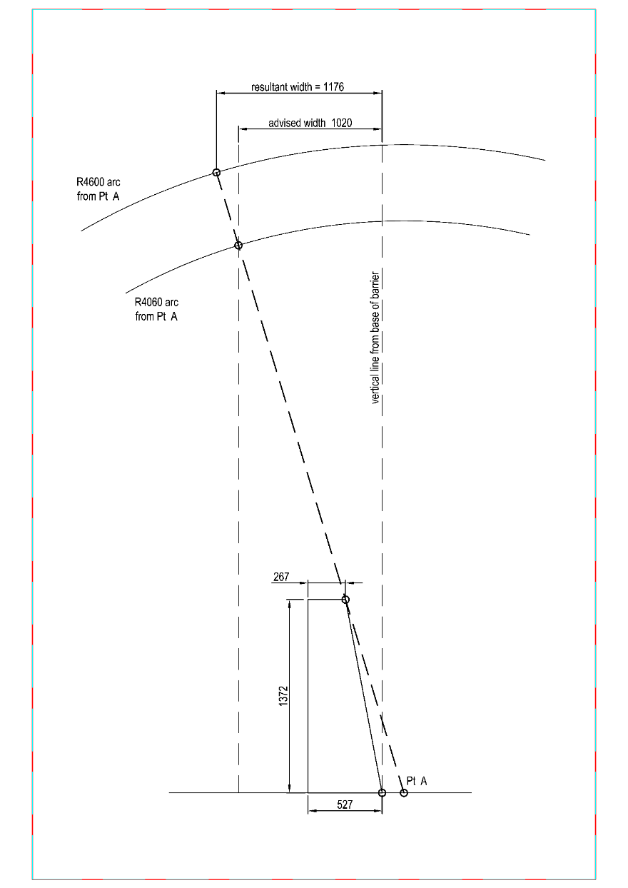
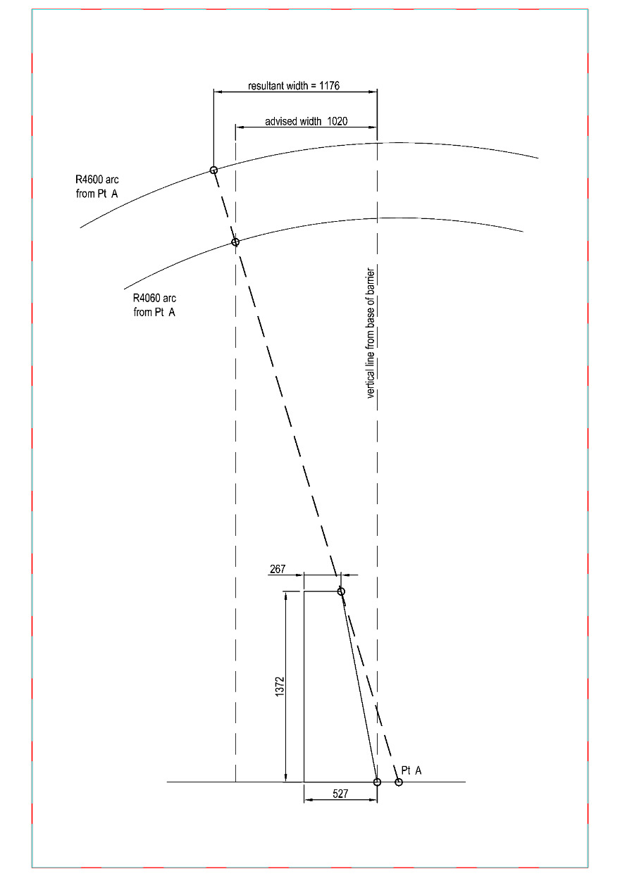
An improved “point of contact” method with roll angle considered is therefore adopted in this study to explore a second method. Firstly the 4060 mm long projected vehicle roll line was extended to 4600 mm, with the roll angle of 16.82° applied (assuming same as the measured value in the Sheikh barrier test), resulting in a working width of 1176 mm for a 4600 mm high vehicle. This process is illustrated in Figure 1 below.
The subsequent steps are same as the extrapolation approach in Method 1. Assuming that the working width is inversely proportional to the barrier height, the barrier height should be increased to 1793 mm to achieve a 900 mm working width for a 4600 mm high vehicle using Equation (3).
BH′=BH×WW×FSWW′
where
BH’ = designed barrier height
BH = tested barrier height (1372 mm adopted in this case)
WW = derived working width of the tested barrier for 4600 mm high vehicle using the “point of contact” method as illustrated in Figure 1 (1176 mm adopted in this case)
WW’ = designed working width (900 mm adopted in this case)
FS = factor of safety (1 adopted for low risk; 1.2 adopted for high risk)
Likewise, if a roadside object is considered a high-risk structure, a factor of safety of 1.2 may be applied so a single slope concrete barrier increases to be 2151 mm high to achieve the 900 mm working width.
Discussion
Application of methodology for varying working widths
The barrier heights derived to achieve the 900 mm working width using both methods are very similar. To investigate the substitutability of these two methods utilised to derive other heights of a single slope concrete barrier to achieve a reduced working width, a sensitivity analysis has been conducted for the targeted working widths of 1400 mm, 1200 mm, 600 mm and 400 mm. The reason for selecting the working widths descending from 1400 mm is that the working width of 1400 mm is the Extended Design Domain (EDD) value recommended in AGRD Part 6 (Troutbeck, 2022b) only when the cargo box is allowed to impact a bridge pier but the cabin shall not. The ratio of the cabin height (2700 mm) to the cargo box height (4600 mm) was multiplied by the working width of 2400 mm under the Normal Design Domain (NDD), resulting in 1400 mm under EDD (TMR, 2023a). As the purpose of this study was to develop an alternative design methodology to address the situations not covered by either the NDD or EDD, it was not considered necessary to assess any working width greater than the EDD value.
Table 4 shows the standard deviation values are close to zero, which proves that statistically, both methods would result in very similar barrier heights for a given working width narrower than the EDD value (≤1400 mm).
Another condition for applying Methods 1 and 2 is that they should be restricted to a single slope concrete barrier with a 1800 mm height and above. This is because the centre of gravity of the cargo box of the 4060 mm high vehicle in the Sheikh barrier test (Sheikh et al., 2019) was approximately 1800 mm above the ground surface and the centre of gravity would tend to result in less roll as the barrier height increases from 1372 mm. Considering the elevated centre of gravity of a 4600 mm design vehicle, the roll angle would be likely increased but also may be concurrently offset, to some extent, by the barrier height increased to 1800 mm or taller, though the effects are unable to be quantified due to the lack of adequate data.
In addition, practitioners should be conscious that the working width will be equal to the system width when the system width is wider than the rollover of the impacting vehicle. Once the system width reaches the target working width (which is greater than 900 mm), further increasing the barrier height may not be necessary. Therefore, practitioners should perform project-specific calculations to determine the appropriate barrier height, ensuring a minimum height of 1800 mm, based on the target working width.
Network-wide asset review
It is recommended that road authorities undertake a comprehensive network-wide review to identify locations where the working widths of single-slope barriers protecting significant roadside structures do not meet current standards. This review should focus on routes with high volumes and high proportion of heavy vehicles, allowing for the prioritisation of road corridors in need of treatment.
Limitations
No new crash tests have been undertaken for the subject TMR barrier to experiment on taller system heights due to a lack of funding. This study relied on the existing data from other’s published works. The source of crash testing data matching the profile of the TMR barrier is limited as only the Sheikh barrier presents a near-identical slope gradient of the traffic face.
The footing design of the Sheikh barrier was assumed to play a role in stabilising the barrier that affected its performance in terms of the resultant working width in the crash test. The structural design is out of the scope of this paper, however, in practice, practitioners should always seek advice from qualified structural designers to either adopt the design of the Sheikh barrier or design the anchorage to achieve equivalence on a case-by-case basis.
Notwithstanding both Methods 1 and 2 were expected to yield very similar barrier heights for a given working width narrower than the EDD value from a statistical perspective, assumptions carry slightly less weight in Method 2. This is due to the working width for a 4600 mm design vehicle derived from the 4060 mm test vehicle based on the “point of contact with roll angle considered” method where the 1800 mm centre of gravity has been taken into account.
Conclusions
This study explored alternative solutions to achieve a reduced working width for a public domain single slope concrete barrier. Specifically when the designed working width was compliant with a prior design guide at the time but now is narrower than the current standards required value. Due to constraints where the offset from the concrete barrier to a significant roadside structure cannot be increased by shoulder widening, increase of the barrier system height within the fixed footprint (i.e., utilisation of vertical space) was employed to avoid the demand to laterally shift the safety barrier away from a roadside structure.
The only available existing crash testing data for a USA single slope concrete barrier was referred as the basis to derive a taller barrier with a theoretically reduced working width. Two methods, the linear extrapolation and the “point of contact” with roll angle considered, were developed and are expected to generate very similar results of system heights for a target working width. The outcome of this study has been acknowledged by TMR and the system height values to achieve a 900 m working width using the methodology introduced in this study have been incorporated in TMR’s technical note as a Design Exception guidance (TMR, 2023b).
It is recommended that physical crash testing or computer simulation be considered for future works to either provide a first-hand data including recorded working width values or validate the above-mentioned design methodology.
Disclaimer
The work presented in the manuscript is based on the authors’ contribution to the development of a technical note published by the Queensland Department of Transport and Main Roads, however, it should be noted that the content of this paper does not represent the views of the State of Queensland or the Department of Transport and Main Roads. All the use of the information by any party for any purpose is at their own risk. The State of Queensland or TMR accepts no liability for decisions made or actions taken in reliance on any information or advice, expressed or implied, contained within. Any opinions expressed are solely those of the authors.
Acknowledgements
The authors would like to thank the Department of Transport and Main Roads, Queensland Government for providing support towards development of this design guidance.
Author Contributions
P. Saba initiated the idea of developing a Design Exception guidance, conceptualised the research strategy and reviewed the research outcome. X. S. Tu undertook a literature review, data analysis, options analysis, development of a recommended design method, and writing the manuscript. S. Tripathi edited the draft paper and supervised the study. All authors have read and agreed to the published version of the manuscript.
Funding
This study did not receive any specific grant from funding agencies in the public, commercial, or not-for-profit sectors
Conflicts of interest
The authors declare there is no conflict of interest.